1. Machine bed and guide rail
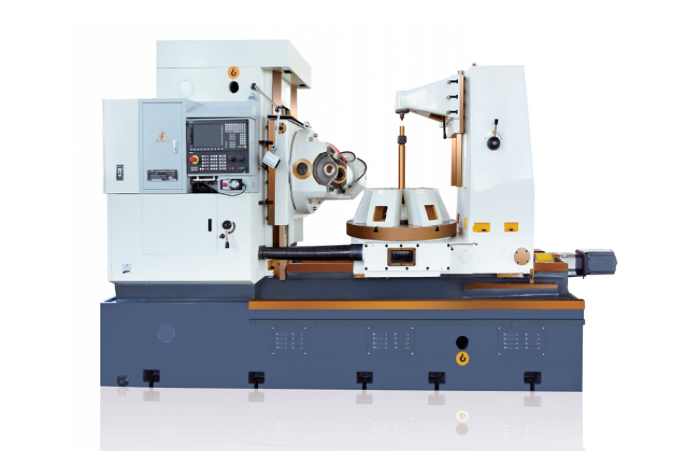
The bed adopts gray cast iron structure.
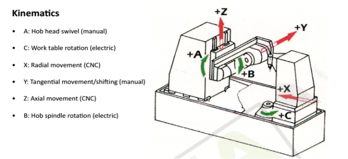
The X axis adopts a large plane rectangular guide rail to meet the rigidity requirements of the machine tool for high-speed, large-pass cutting.
The high-precision ball screw for X-axis radial feed is fixed on the bed, and the special bearing group is pre-stretched in both directions.
Driven by Siemens servo motor, the planetary reducer reduces the speed, and drives the ball screw to move the column back and forth.
The bed is equipped with a retractable steel protective cover.
Adjustable fastening bolts are used to fix the bed to the foundation.
2. Column
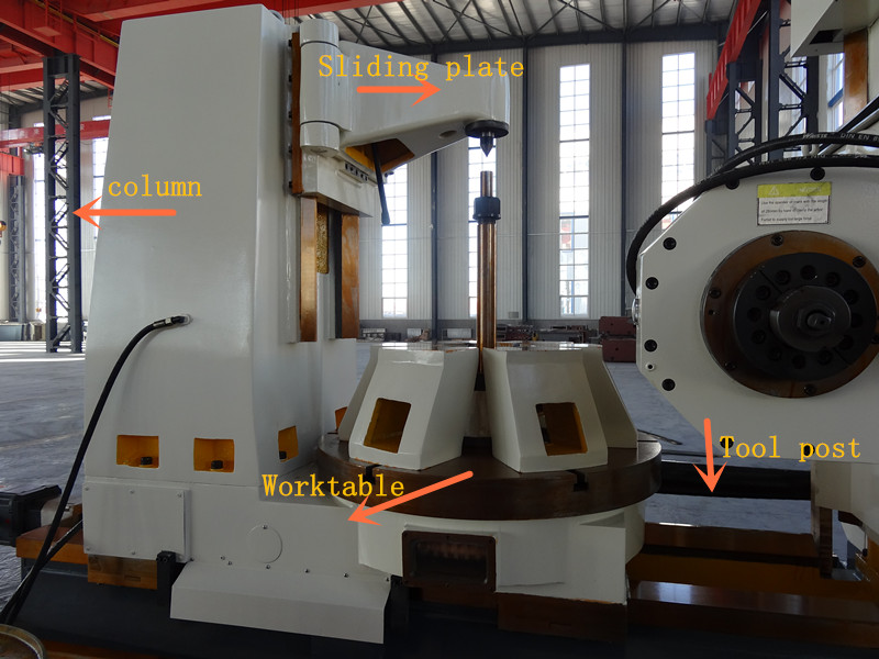
The column moves on the guide rail of the bed and adopts the overall gray cast iron structure.
A low-friction special material is pasted on the guide rail, so that the column can move freely.
Z axis adopts a large plane rectangular guide rail, the high-precision ball screw for Z-axis axial feed is fixed on the bed, driven by Siemens servo motor, the speed of the worm gear pair is reduced, and the ball screw is driven to realize the up and down movement of the carriage slide.
3. Reel holder and tool holder slide (Z axis)
The hob rest is installed on the sliding seat of the tool rest, the sliding seat moves up and down on the column guide rail, and the main body adopts an integral gray cast iron structure.
The tool holder can rotate ±45° on the sliding seat (A-axis) and rotate automatically.
The design structure of the tool holder sliding seat is convenient for the replacement of various tool holders.
A low-friction special material is pasted on the slide rail of the tool holder.
The tool holder has its own power, and the tool holder is driven by a servo spindle motor with infinitely variable speed.
The tool holder uses the shortest hob spindle drive chain, bearing support structure and anti-backlash mechanism to achieve the high speed and anti-vibration requirements of the hob spindle system.
The radial support of the hob spindle is hydrostatic support.
The tangential movement of the tool holder (Y axis) uses a "V" and a flat guide rail structure and drives the hob box through a servo motor, a planetary reducer and a ball screw. The Y axis has a hydraulic automatic clamping and releasing mechanism.
4. Feeding mechanism
X, Y, Z direction feed drive is driven by Siemens AC servo feed motor, ball screw drive, special bearing set for high precision ball screw, bidirectional pre-stretching.

5. Worktable (C axis)
High-precision double-lead worm gear pair, the worktable adopts a hydrostatic bearing support structure in the radial and axial directions, which realizes the gap-free transmission of the worktable and meets the requirements of tooth cutting accuracy.
The worktable has a stable structure and good rigidity so that the cutting force can be better absorbed and transmitted directly to the base of the machine tool. It has a good cutting force damping effect and strong rigidity.

6. Lubrication system
Independent circulating lubrication system and quantitative lubrication system; quantitative lubrication for ball screw and main guide rail pair, adjustable lubrication time interval; continuous lubrication for tool rest transmission parts and bearings; sufficient and reliable lubrication, and fault detection and alarm system.
The pressurized circulation of lubricant and coolant ensures optimum thermal stability throughout the hobbing cycle.
7. Cooling chip removal system
Two sets of large-flow, high-lift cooling pumps are used for machine tool cooling, which can be used independently or at the same time. The coolant recovery system is stable and reliable.
Compressed air can be used for cooling when milling teeth.
Equipped with an automatic chip removal unit, which automatically separates and discharges chips.
8. Hydraulic system and function
The main control components of the hydraulic system are made of Taiwan Asada products or other international famous brand products, which are stable and reliable.
The hydraulic system is equipped with an oil cooling device.
Hydraulic system function:
- Workbench static pressure
- Tool holder spindle static pressure
- Clamping mechanisms such as column and tool holder
- Lubrication of each part
- Other auxiliary functions
9. Guards
The machine door can be opened and closed manually, and the protective door can be opened flexibly;
The machine tool adopts a semi-enclosed protective cover to prevent the leakage of chips, coolant and oil mist;
The operating surface of the shield has a transparent observation window, and the processing area is illuminated for easy observation;
The protective door of the machine tool is equipped with an electronic lock to interlock with the start of the machine tool, that is, the machine tool can only be started when the protective door is closed, and the protective door cannot be opened during processing;
The pedals, escalators and railings are firm and reliable, and the design is reasonable and beautiful.


